Body of an internal combustion engine for performing the air-fuel mixture
1. Describe and master the operation of the circuits of a carburetor
2. Check and adjust idle speed
3. Adjust the carburetor circuits to meet emissions standards
4. Define and know the origin of harmful gases from gasoline engine exhaust.
5. Understand the importance and usefulness of anti-pollution standards.
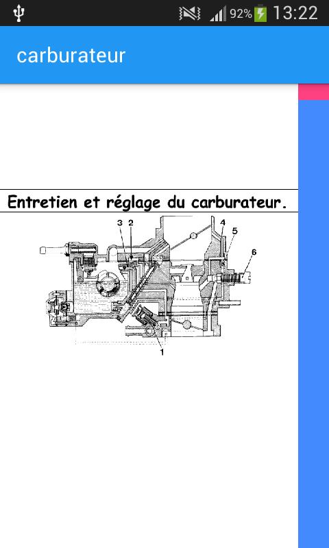
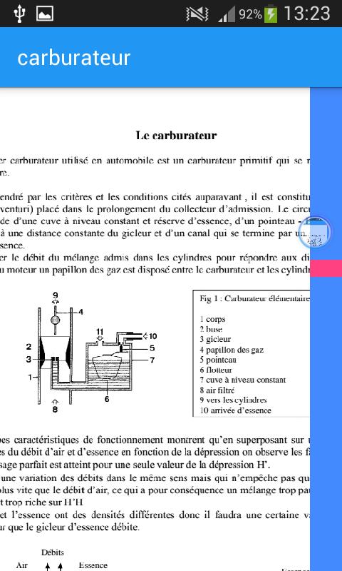
1 body 2 nozzle 3 nozzle 4 throttle valve 5 needle 6 float 7 constant level tank 8 filtered air 9 to the cylinders 10 fuel supply
Starting at low temperature (approximately 0°)
Resumption
At low speed
In slow motion
Maximum power
Economical driving
Drowned sprinkler
1 Body 2 Nozzle 3 Nozzle 4 Throttle valve 5 Needle 6 Float 7 Level tank 8 Filtered air 9 To the cylinders 10 Fuel inlet 11 bringing to atmospheric pressure 12 automaticity nozzle
The idle circuit
It allows the engine to remain in rotation when the vehicle is stationary but also progress when going from idle to normal running and during deceleration the fuel supply system is taken either: Directly in the tank: it will be called the “two-jet system” since it will flow both at idle and normal running. Only in the main circuit pipe and after the nozzle: it will have the name “monojet system” and will not flow during normal operation
1 Air calibrator 2 Idle jet 3 Main jet 4 Richness screw 5 By pass 6 Throttle valve stop screw 7 Non-spilling port
Sweeping slow motion
Idling at constant CO
Wealth correctors
1 Suction valve 2 Control rod and spring 3 Adjusting nut 4 Control lever 5 Diaphragm 6 Spring 7 Delivery valve 8 Injector
1 Membrane 2 Vacuum tap
Cold start devices
The starter
ice starter principle
1 Emulsion outlet channel 2 Fuel line 3 Glass 4 Air nozzle 5 Housing 6 Rotating glass 7 Fuel nozzle 8 reserve (well)
Ice system 1 Fuel inlet 2 Notch 3 Choke control 4 Cold start position 5 Intermediate position 6 Choke cut arrangement
the starting pane
1 Outlet damper 2 Lever 3 Return spring 4 Outlet air inlet
1 Flap 2 Flap 3 Spring
1 OVAD (Opening of the After Start Flap) 2 Membrane 3 OVAD adjustment screw 4 Spring
The spring holds the membrane in the rest position for starting the engine. As soon as the latter can take charge, the depression increases rapidly and causes the membrane to move back to a value set by the stop screw.
Carburetor adjustment
The adjustment is made after the carburetor is in good condition and before it is reinstalled on the engine. For these pre-adjustments we will use specific tools such as gauges, calibrators and angle measurers. The adjustments to be made relate to: The position that the throttle valve takes during: Idling Cold start, positive opening and half-opening of the shutter At the level of the tank At the recovery pump To make these adjustments you will need to refer to the data in the manufacturer's technical sheets
Adjusting the tank level: The needle and the float having been checked, the height which exists between the float and the surface of the tank joint must be controlled by gauges or rods. This height can be adjusted: By forming the float rocker; By action on the needle attack tab; By modifying the thickness of the needle seal.
Recovery pump settings
Read more